Detailed mechanical design
Models, dimensions, tolerance decisions, materials, assembly details, and a reviewed load path.

A concept for a bench fixture that locates a component, applies a controlled load, and records a force measurement. Follow the interfaces and the questions an engineering package must resolve.
Concept study. Not a built, validated, or released customer design.
01 / Establish the requirements
A test station is only useful when its product interface, measurement needs, and acceptance method are defined. This study identifies decisions to resolve before detailed design.
| Requirement | Design consequence | How to evaluate it |
|---|---|---|
| Locate the product consistently | Define datum surfaces, locators, clamping, and loading access. | Repeated loading trials and inspection against an agreed location tolerance. |
| Apply the intended load | Size the structure and actuation for the agreed load, travel, and load path. | Calculations, component review, and physical trials against the load profile. |
| Measure force meaningfully | Select sensor range, mounting, signal conditioning, and acquisition settings. | A calibration and measurement-uncertainty plan appropriate to the acceptance limits. |
| Run a defined test sequence | Specify operating states, operator actions, fault responses, and data records. | Sequence review and commissioning tests for normal and fault conditions. |
02 / Coordinate the architecture
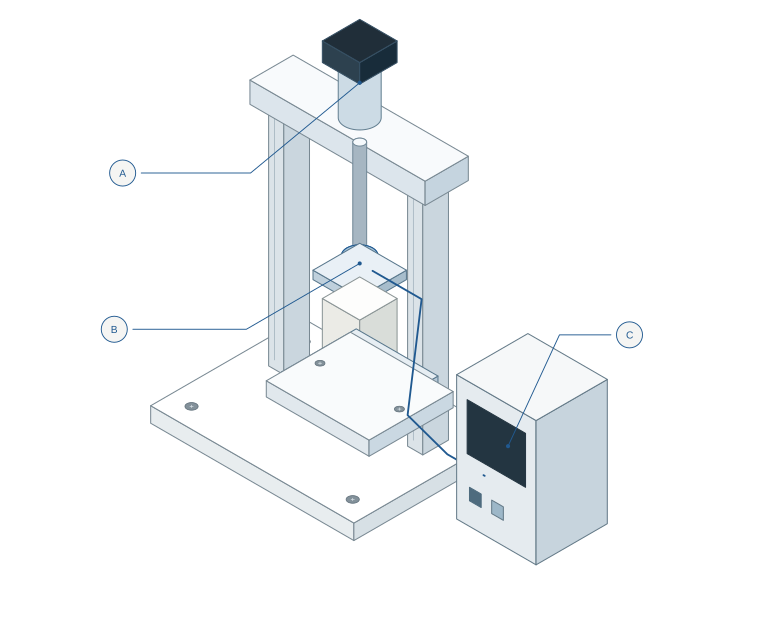
The illustration shows a possible arrangement. Final geometry, component selection, operating limits, guarding, and test methods would be developed for a specific product and application.
| Assembly | Selection depends on |
|---|---|
| Base & structure | Load path, stiffness, envelope, mounting. |
| Product tooling | Datum scheme, product geometry, access. |
| Guided actuator | Force, stroke, speed, duty cycle. |
| Force sensor & acquisition | Range, overload, uncertainty, signal interface. |
| Controls & enclosure | Power, I/O, operating sequence, risk assessment. |
03 / A requirement changes
Suppose the required test load increases. Updating the actuator alone would leave several connected decisions unresolved. This is the kind of coordination the Rocavo AI Engine is being developed to support.
Reassess the fixture for a higher force requirement, while retaining the product interface and measurement objective.
The engineering task is to identify affected work, revise the design basis, and define the checks required before accepting the change.
This is an explanatory dependency walkthrough. It does not represent an executed Engine run or a verified design change.
Test fixture engineering ↗04 / From concept to deliverable
The next work would resolve product-specific inputs and produce reviewed design outputs. These items describe a possible project scope; they are not downloadable deliverables from this concept study.
Models, dimensions, tolerance decisions, materials, assembly details, and a reviewed load path.
Connections, power, I/O, instrument interfaces, state sequence, and agreed software deliverables.
Selected parts, a bill of materials, procurement information, assembly instructions, and revision control.
Design checks, risk review, calibration needs, and physical tests with agreed limits and responsibilities.
Your product. Your test.
Share the product, the test objective, and any existing procedure or equipment. We’ll help identify the engineering work needed.
Discuss a test fixture